Warning: WP_Syntax::substituteToken(): Argument #1 ($match) must be passed by reference, value given in /home/pacs/mma00/users/panotwins/doms/panotwins.de/subs/wp/wp-content/plugins/wp-syntax/wp-syntax.php on line 380
One problem with the Sony NEX 5 camara series is the lack of a decent remote shutter mode. You are able to switch it to IR mode and use the IR remote control to take a picture. However you can’t combine any of the other available trigger modes like bracketing or high speed trigger with the IR remote control. I wanted to change this and started this project described here: The ultimate remote trigger for the Sony NEX 5 using a servo and an arduino board. I called this project The Ultimate Trigger V1.
 The Ultimate Trigger V1 is licensed under a Creative Commons Attribution-ShareAlike 3.0 Unported License.
The remote control has four different possibilities for taking a picture:
- Software – Via code running on a host computer sending commands to the COM port where the arduino is attached
- Arduino – Via code running on the arduino itself (not implemented at the moment)
- IR remote – Via an arbitrary IR remote control
- Cable – Via an attached remote release cable
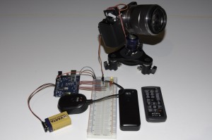
The following image shows the finished breadboard version. You see the arduino board in blue on the left above the yellow 9V battery. Between the arduino board and the battery is the attached wireless remote receiver. In the middle you find the white breadboard with the necessary electronics. On the NEX you see the servo attached via a cable strap and a rubber band. On the right you see the wireless remote transmitter and the IR remote transmitter.
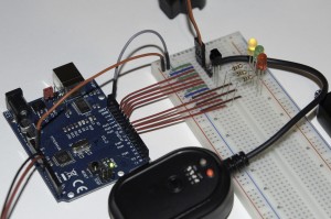
This image shows the breadboard in detail: On the breadboard you find from top to bottom:
- The attached servo (a JR type model with brown, red and orange cables)
- The attached wireless receiver. This could also be any other type of Minolta, Konica-Minolta or Sony remote cable release. The receiver is a third party RF wireless type.
- The IR receiver able to receive most types of consumer IR remote controls.
- Three status LEDs with the necessary series resistors.
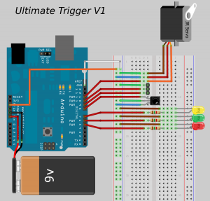
This image shows the breadboard design in detail. It has been made with Fritzing.
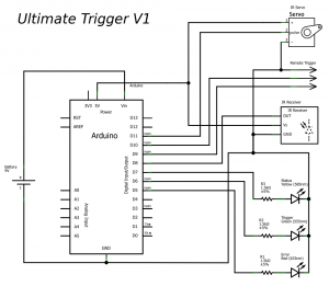
This image shows the schematics of the electronics (also made with Fritzing).
The following code for the arduino sketch makes use of two libraries: Servo (included in the arduino IDE) and IRremote!
/* * Ultimate Trigger V1 * by Markus Matern aka PanoTwin Markus * * Release: 20120107 * * This code is licensed under the Creative Commons Attribution-ShareAlike 3.0 Unported License. * To view a copy of this license, visit http://creativecommons.org/licenses/by-sa/3.0/ * or send a letter to: * Creative Commons, 171 Second Street, Suite 300, San Francisco, California, 94105, USA. */ #include <Servo.h> #include <IRremote.h> // Servo configuration const int servoPin = 11; const int minimumAngle = 0; const int maximumAngle = 179; const int zeroAngle = 100; const int wakeUpAngle = 107; const int shootAngle = 110; Servo myservo; // Wireless remote configuration const int triggerWhite = 10; const int triggerBlue = 9; int whiteVal = LOW; int blueVal = LOW; // IR receiver configuration int RECV_PIN = 8; IRrecv irrecv(RECV_PIN); decode_results results; // Diagonstic configuration const int ledStatus = 7; const int ledTrigger = 6; const int ledError = 5; void setup() { // Diagnostic setup pinMode(ledStatus, OUTPUT); digitalWrite(ledStatus, HIGH); pinMode(ledTrigger, OUTPUT); digitalWrite(ledTrigger, LOW); pinMode(ledError, OUTPUT); digitalWrite(ledError, LOW); // Servo setup myservo.attach(servoPin); myservo.write(zeroAngle); // Wireless setup pinMode(triggerWhite, INPUT); // make sure the input pin is not undefined digitalWrite(triggerWhite, HIGH); pinMode(triggerBlue, INPUT); // make sure the input pin is not undefined digitalWrite(triggerBlue, HIGH); // IR receiver setup irrecv.enableIRIn(); // Start the receiver // Serial setup Serial.begin(9600); } void shoot(){ StatusTrigger(1); myservo.write(wakeUpAngle); delay(1000); myservo.write(shootAngle); delay(1000); myservo.write(zeroAngle); StatusTrigger(0); delay(1000); } void wakeUp(){ StatusTrigger(1); myservo.write(wakeUpAngle); delay(1000); myservo.write(zeroAngle); StatusTrigger(0); delay(1000); } void minAngle(){ StatusTrigger(1); myservo.write(minimumAngle); delay(1000); myservo.write(zeroAngle); delay(1000); StatusTrigger(0); } void maxAngle(){ StatusTrigger(1); myservo.write(maximumAngle); delay(1000); myservo.write(zeroAngle); delay(1000); StatusTrigger(0); } void Blink(int blinkLed, int milliseconds, int blinkCount) { for(int i = 0; i < blinkCount; i++) { Status(blinkLed, 1); delay(milliseconds/blinkCount/2); Status(blinkLed, 0); delay(milliseconds/blinkCount/2); } } void BlinkBeforeTrigger(int milliseconds) { Blink(ledTrigger, milliseconds, 3); } void StatusTrigger(int newStatus) { Status(ledTrigger, newStatus); } void StatusError(int newStatus) { Status(ledError, newStatus); } void Status(int pin, int newStatus) { if(newStatus){ digitalWrite(pin, HIGH); } else { digitalWrite(pin, LOW); } } void loop() { // remote control via serial communication if (Serial.available() > 0) { int b = Serial.read(); switch(b) { case 't': shoot(); break; case 'w': wakeUp(); break; case '0': minAngle(); break; case '8': maxAngle(); break; default: Blink(ledError, 600, 3); break; } Serial.flush(); } else if (irrecv.decode(&results)) { switch(results.value) { // Sony Shutter (2 Sec) case 0xECB8F: StatusTrigger(1); Blink(ledTrigger, 2000, 4); // Note: No break here! // fall through to shoot! // Sony Shutter case 0xB4B8F: shoot(); break; case 0: break; default: StatusError(1); Serial.println(results.value, HEX); Blink(ledError, 600, 3); StatusError(0); break; } // Receive the next value irrecv.resume(); } else { // Check the wireless remote trigger int newWhiteVal = digitalRead(triggerWhite); int newBlueVal = digitalRead(triggerBlue); if (newWhiteVal != whiteVal) { if (newWhiteVal == HIGH) { //Serial.println("White High"); myservo.write(zeroAngle); StatusTrigger(0); } else { //Serial.println("White Low"); StatusTrigger(1); StatusError(0); myservo.write(wakeUpAngle); } whiteVal = newWhiteVal; } if (newBlueVal != blueVal) { if (newBlueVal == HIGH) { //Serial.println("Blue High"); StatusError(0); } else { //Serial.println("Blue Low"); myservo.write(shootAngle); StatusTrigger(1); StatusError(1); } blueVal = newBlueVal; } } } |
